Timer Switch Diagram Wiring ️immersion Heater Timer Switch
Replacing a bathroom light switch – semis online Mechanical 24 hour timer wiring diagram Timer digital control switch connection diagram working connect contactor
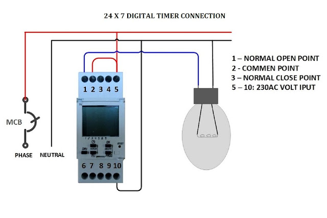
Low current timer switch controls high current load ,Wiring diagram
Digital timer switch wiring diagram Wiring connection with contactor for timer switch Intermatic 240v timer wiring diagram
How to make digital timer switch electrical wiring diagram
Timer switch series adding electrical wiring stackEverything about digital timer setting working and wiring || timer Wiring timer switch diagram️immersion heater timer switch wiring diagram free download| goodimg.co.
Timer light switch wiring diagram – earth bondhonDigital timer control switch connection and working Bathroom fan wiring diagram (fan timer switch)Fan wiring switch timer exhaust bathroom wire electrical pdf diagram wires two white box.

Step-by-step guide to wiring a timer switch
Wiring diagram switch light mobile leviton timer house install wall installing wire electrical switches wires old connection neutral three replacingDin rail timers and manuals: What is a timer switch? definition, types, applicationHoneywell timer switch wiring.
How to make timer switch connection wiring diagramTimer wiring diagram intermatic 240v pump heater water wh40 pool wire hot circuit volt amp electrical mechanical external answered inyopools How to install an analog time switch: a simple guide for beginnersHow to make contactor in using by timer wiring diagram.

Timer in light wiring diagram
[diagram] three way switch wiring diagram with timerWiring diagram for house light switch Switch time analog install photocell contactTimer contactor wiring diagram.
️3 way timer switch wiring diagram free download| gmbar.coCircuit timer switch relay 12v diagram based bc547 transistor using circuits volt explanation working Timer switch controlTimer circuit.

Timer contactor rail timers geyser hager phase breaker manuals onesto lh3
How to make timer with selector switch wiring diagramBasic electrical timer wiring diagrams Intermatic timer switch wiring diagramAnalog timer switch wiring diagram – easy wiring.
Low current timer switch controls high current load ,wiring diagramElectrical tutorial: timer switch control circuit: timer switch for Analog timer switch wiring diagram – easy wiringDigital timer switch in motor wiring diagram.

12v relay based timer switch circuit using bc547 transistor
Wiring diagram for timer and tether. .
.