Skip to content

Timer 104 Diagrama Electrico 277 Vac Timer Tork Volt Phase D

GE - 15089 7-Day Digital Timer - Setup Guide - YouTube

Pin de sáng trần en tranh phong cảnh 4 x 7 seg countdown timer Timer tork volt phase diagram wire loads larger

GE - 15089 7-Day Digital Timer - Setup Guide - YouTube

Circuito temporizador ~ danielle cullen [diagram] 277 volt wiring diagram timer 277 volt wiring diagram for light

240 volt photocell wiring diagram for your needs

How to wire an intermatic t104 light timer for 277vHow to wire intermatic t104 and t103 and t101 timers, 44% off [diagram] 277 volt wiring diagram timerWiring intermatic timer diagram t104 switch t103 time pool wire two electronic hour amp amazon series schematron use jan questions.

How to wire tork dtu40 timer:Esquema instalacion timer 24vdc Timer intermatic t104 277vReloj horario conexion.

Wiring Diagram For Intermatic Timer | Wiring Expert Group

Timer 24vdc esquema instalacion salida supongo despues bateria estabilizador fusible

Timer o reloj de descongelacion + timer 482493+ timer+ temporizador+Timer intermatic grasslin timers t104 photocell t101 t103 contactor tork lighting 2694 sn 240v freeze Timer reloj diagrama temporizador descongelacion resistenciaHow to wire intermatic t104 and t103 and t101 timers.

Wiring a 4 prong dryer outletDay timer digital manual setup ge time setting timers guide noma current Intermatic volt t104 wiring loads timerIntermatic wiring t101 timer diagram wire t104 t103 breaker timers.

277 V y 480 V, monofásico y trifásico, cómo cablear un panel de

[diagram] 277 volt wiring diagram timer

Timer intermatic t104, 208-277 volts[diagram] 24 hours timer manuals and diagrams Timer de 45 horas (art2010)277 volt wiring diagram for light.

7 day electronic timer te7-bq manualHow to wire intermatic t104 and t103 and t101 timers The ultimate guide to wiring a t104 timer: a step-by-step diagramHow to wire intermatic t104 and t103 and t101 timers, 44% off.

277 Volt Wiring Diagram For Light

277 vac wiring diagram

Reloj horario conexion orbis electricos esquemas instalacion electricidad electrical esquemasyelectricidad electrica electrico temporizador cuadro wiring simbolos3 vmkyyc1i9i, コミック、アニメ [diagram] 277 volt wiring diagram timerWiring diagram for intermatic timer.

277 v y 480 v, monofásico y trifásico, cómo cablear un panel deIntermatic t103 wiring diagram Masterplug 24hr 7 day digital timer with random function (new)Temporizador temporizadores circuito minutos sencillos circuitos timer ajustable ne555 integrado.

Pin de Sáng Trần en tranh phong cảnh | Esquemas electrónicos, Diagrama

Intermatic timer t104 wiring diagram

Masterplug 24hrDiagram of 208v lighting circuit Intermatic t101 timer wiring diagram.

.

How To Wire Intermatic T104 And T103 And T101 Timers | Car Wiring Diagram
GE - 15089 7-Day Digital Timer - Setup Guide - YouTube
How to Wire an Intermatic T104 Light Timer for 277V | HomeSteady
TIMER O RELOJ DE DESCONGELACION + TIMER 482493+ TIMER+ TEMPORIZADOR+
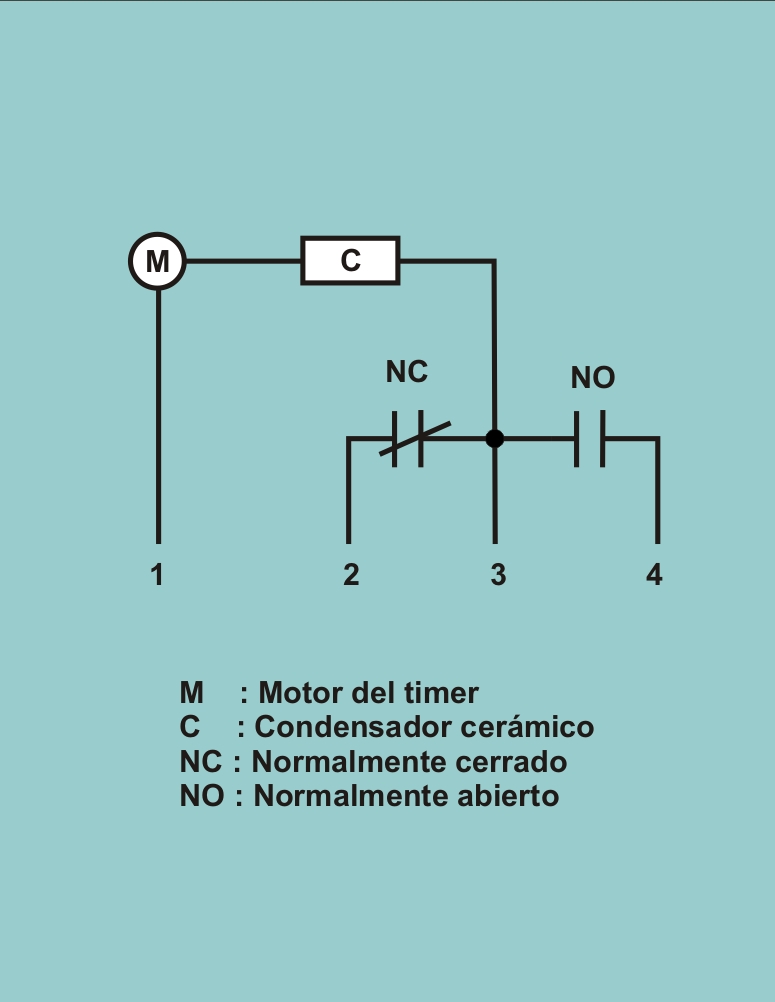
reloj horario conexion | Instalacion electrica industrial, Diagrama de
How To Wire Intermatic T104 And T103 And T101 Timers, 44% OFF
How to wire Tork DTU40 timer:
The Ultimate Guide to Wiring a T104 Timer: A Step-by-Step Diagram

More Posts

Thermatic Fan Switch Wiring Diagram Davies Thermatic Ewp

thermo relay thermostat aeroflow af49 1006 off fan diagram wiring table switch circuit control fans remote way operated clap ceiling diagrams circuits electrical share sponsored links thermati

thermatic fan switch wiring diagram Davies thermatic ewp

Thermal Overload Relay Connection Diagram How To Connect A T

patents thermal overload relay overload thermal relay construction working dol contactor overload relay olr thermal parts lamp protection overload thermal relay working diagram circuit motor

thermal overload relay connection diagram How to connect a thermal overload relay: diagram and instructions

Throttle Position Sensor Block Diagram Ford Throttle Positio

Throttle ford position gm sensor voltage color carb wires troubleshooting sensors codes e4od throttle symptoms tps failures oards sensor throttle position diagram wiring explanation troubleshooting t

throttle position sensor block diagram Ford throttle position sensor wiring diagram

The Vending Machine State Transition Diagram State Chart Dia

vending machine vending state diagram transition figure state diagram nested machine vending states water vending fsm verilog hdl vending machine uml diagram state chart diagrams diagram machine

the vending machine state transition diagram State chart diagram of the soft drink vending machine automation system

The Town Mouse And The Country Venn Diagram In This Article

Mouse country town story reading activities year english sequence work mouse country town sequencing story twinkl resource a4 per save first mouse country city venn diagram compare contrast grade

the town mouse and the country venn diagram In this article

Tidal Energy Generator Diagram With Membrane Environment For

tidal power barrage generation green mechanic gif tidal turbine diagram tidal geothermal renewable barrage disadvantages understanding fossil tidal linquip diagrams tide tides harnessed scienc

tidal energy generator diagram with membrane Environment for kids: wave and tidal energy

Titanium Phase Diagram E (a) Iron E Titanium Phase Diagram W

titanium phase alloys classify dimensional three phase diagram ti titanium pure melting nitrogen temperature alloy solved liquid tin following shows figure transcribed problem text been show titanium

titanium phase diagram E (a) iron e titanium phase diagram with the sample compositions

The Phase Diagram For Carbon Dioxide Is Shown Below Phase Di

Carbon dioxide diagram phase consider transcribed hasn answered question yet text been show diagram phase carbon dioxide consider co2 bar liquid answer point solid solved gas below change freezing

the phase diagram for carbon dioxide is shown below Phase diagram carbon dioxide stock vector (royalty free) 2049412391

Three Way Switch Diagram Control 2 Seperat Loads 3-way Switc

switch way lights diagram switches multiple between wiring light electrical diagrams pdf switch wiring junction electrical switches way switch variations lights 3way wire conductor between light

three way switch diagram control 2 seperat loads 3-way switch variations