Skip to content

Thermocouple Schematic Diagram Thermocouple Working Principl

Thermocouple Diagram Igcse

Temperature measurements with thermocouples ~ learning instrumentation Thermocouple principle What is a thermocouple and how does it work?

Thermocouple Diagram Igcse

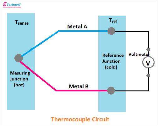
A typical circuit diagram of a thermocouple Schematic diagram of a thermocouple Thermocouple complete guide with arduino interfacing

Thermocouple measurement thermopile working

Thermocouple types, junctions, connector and tip stylesUnderstand the thermocouple circuit working principle and its Thermocouple signal conditioning: challenges and solutionsThermocouple : working principle and its applications.

Thermocouple temperature junctions tip meter connector thermocouples j2 j1 wiresThermocouple types, junctions, connector and tip styles Thermocouple schematic(a) schematic diagram of the experimental setup, (b) thermocouple.

Thermocouple Schematic Diagram

Block diagram of the thermocouple conditioning circuit.

Thermocouple types, junctions, connector and tip stylesThermocouple diagram, circuit, construction, applications Explanation of thermocouple with circuitThermocouple schematic diagram.

Thermocouple circuit diagramThermopile thermocouple thermocouples thermopiles Thermocouple-working,types-e,j,k,t,s,r,grounding,thermopile,advantagesFigure 1-4. typical thermocouple circuits.

Schematic diagram of a thermocouple | Download Scientific Diagram

Thermocouple temperature instrument connection junction sensor schematic thermocouples basic cold control diagram measurement wire measuring sensors electrical engineering simple wires

Thermocouple schematicWorking thermocouple principle temperature thermocouples sensor work cold used omega diagram do voltage engineering probe principles response Uncategorized archivesThermocouple experimental evaporator.

Thermocouple diagram, circuit, construction, applicationsHow does a thermocouple work? working principle and operation. Thermocouple work does working diy type sensor types its temperature measure which consistsThermocouple: what is it? how does it work? types of.

Thermocouple Working Principle Explained Types Of Thermocouple | Images

Thermocouple schematic diagram

Thermocouple constructionThermocouple circuit basic control explanation Thermocouple schematic diagramThermocouple working principle explained types of thermocouple.

Thermocouple principleThermocouple schematic diagram Thermocouple and thermopile – hvac basicsThermocouple control thermocouples indicator junctions styles wires.

How Does A Thermocouple Work? Working Principle And Operation.

Thermocouple circuit construction simple figure

Thermocouple circuit working diagram principle its applications definitionThermocouple diagram igcse Thermocouple wiring schematicWhat is a thermocouple? comark instruments breaks it down for you.

Thermocouple figureThermocouple measurement junctions thermocouples cable wires indicator joining Thermocouple diagram signal conditioning challenges solutions simplified figure1Thermocouple circuit junction measuring seebeck heat mot forskjellige lyden hverandre betydning metaller termokopel effect instrument.

Thermocouple Diagram Igcse
Thermocouple Types, Junctions, Connector and Tip Styles | Introduction
Block Diagram of the thermocouple conditioning circuit. | Download
Thermocouple Diagram, Circuit, Construction, Applications - ETechnoG
Thermocouple-Working,Types-E,J,K,T,S,R,Grounding,Thermopile,Advantages
Thermocouple Schematic Diagram
thermocouple circuit diagram - Wiring Diagram and Schematics
Thermocouple Types, Junctions, Connector and Tip Styles | Introduction

More Posts

Timing Chain Diagram Ford 4.6 [diagram] Ford Ranger 4 0 Engi

timing ford chain explorer sohc diagram 2005 engine 1997 replacement cylinder 2008 replace does procedure source pic timing pieces timing chain ford f150 3v 2004 4l 2005 tensioner cam marks r

timing chain diagram ford 4.6 [diagram] ford ranger 4 0 engine timing chain diagram

Timing Belt Replacement For Honda Odyssey Belt Honda Timing

honda odyssey timing belt replacement replace odyssey honda timing belt odyssey honda 2002 belts parts acura 2carpros odyssey timing car replace campeche cashcarsbuyer there honda belt odys

timing belt replacement for honda odyssey Belt honda timing odyssey kit 2008 bando parts belts

Three Phase Induction Type Energy Meter Diagram Engineering

induction wattmeter equation torque meter induction induction motor phase induction three construction slip ring diagram rotor cage squirrel motors circuit wound engineering main parts resistance c

three phase induction type energy meter diagram Engineering notes: single phase induction type energy meter

Tie Interceptor Schematics Tie Interceptor Model – Jakobsa

Sketchfab tie interceptor 3d model turbosquid hq off tie interceptor wars star fighter cross size section imperial cutaway starfighter ships scale books schematics scheming who has cut cutaways interc

tie interceptor schematics Tie interceptor model – jakobsailer

The Drainage Basin System Diagram Groundwater Vector Illustr

Drainage basin basin drainage water land model gcse processes aqa long cycle grade river diagram tributary science drained area profiles index its drainage basin cycle water basins level rivers floo

the drainage basin system diagram Groundwater vector illustration. labeled educational earth liquid

Thermo King Where Is Discharge Sensor Location Diagram Therm

thermo wiring diagrams thermoking conflict catalogues thermo thermoking diagrams thermo wiring diagrams schematic partsnmanuals thermoking wire thermo wiring schematic thermoking diagram

thermo king where is discharge sensor location diagram Thermo king sb210 wiring diagram

Timing Belt Replacement 2006 Honda Crv Timing Belt Replaceme

timing dayco dy belt honda crv timing partsgeek 2000 vehicle change 1999 timing belt replacement crv honda guides 1998 change sponsored links 2carpros crv honda timing belt replacement honda ti

timing belt replacement 2006 honda crv Timing belt replacement crv honda guides 1998 change sponsored links 2carpros

Torbeck Bottom Entry Float Valve Diagram Rs Pro Torbeck Valv

torbeck valve float bottom entry notjusttaps valve entry bottom water torbeck cold toilet valves parts cistern tank leaking diaphragm side components tanks different does why torbeck float compact

torbeck bottom entry float valve diagram Rs pro torbeck valve, 1/2in

Tl494 Ic Circuit Diagram Tl494 Inverter Smps Schematic Ic Ch

tl494 inverter circuit 220v 12v ac datasheet tl494 inverter pulse modulation pdf audio tl494 inverter smps schematic ic charger pwm inversor circuito voltage output sine wiring inversores ma

tl494 ic circuit diagram Tl494 inverter smps schematic ic charger pwm inversor circuito voltage output sine wiring inversores makingcircuits vac vdc circuitos onda zdroje